Home
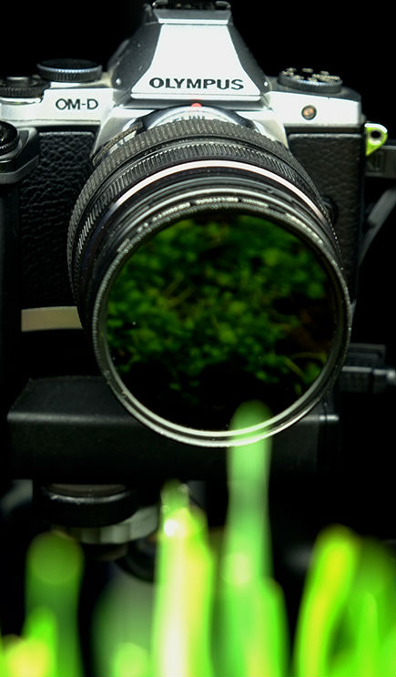
My Equipment
Showcase
Bio-Lapse Blog
Getting Started. 2013
Introduction
Hyancinth First Biolapse
Getting back on the horse
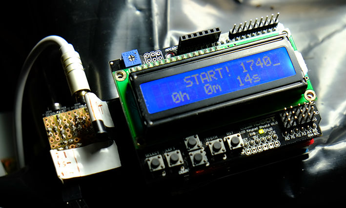
Greenthumb Prototype
Playing in the Dirt
Moving on to Moss
Flicker is getting worse
DIY Humidifier
Up and Running, 2014
Building the BMC
Illuminating unexpected friends
PaperWhites
Days 1-5
Days 5 through 10
From the Womb to the Tomb
Who am I?